Air Piston Water Gun Mk1
“Gladius”
This is the Gladius. It is a light, compact water gun that produces extremely high water output for its size. It works like a typical super soaker: drawing water from a reservoir, pressurizing it, and firing it out a front-mounted valve.

Creating an effective water gun has been on my mind for a while. My family’s competitive nature mingled with my creative side, resulting in an enticing opportunity to one-up people and explore the technical side of propelling water.

This is a small part of my competitive family. Three of us brothers and one sister in law are geared up for a water war at camp. I’m near the right with the camouflage dreadlocks hanging off my hat, holding what I consider to be the finest [water] battle implement ever devised: the CPS-1000.

For those who aren’t strangely well acquainted with super soaker technology, the CPS-1000 was a sweet machine. In numbers, it would hold 2 liters of water in the reservoir, and could shoot up to 600mL of it at a time, with a flow rate of 200mL/second. It was made in 1997 or so, and unfortunately modern water guns are kind of a joke compared to it. A contemporary Super Soaker Lightning Storm can only output 9mL/second.
Anyways, the CPS-1000 is in fact the middle of its product line, staying comfortably light despite its power. There were several super soakers far more powerful, but I consider them too encumbering to be able to stay mobile.
The goal of this whole exercise was to create a water gun with the same design principles: lightweight, compact, yet high performance.
Design
The Gladius was designed to be a high performance water gun. The water gun’s design philosophy as a compact and effective weapon draws similarities to the eponymous Roman sword; in its day a basic, lightweight weapon designed primarily for thrusting attacks.
The CPS-1000, mentioned in a love letter disguised as the introduction, is powered by a thick elastic bladder. Some earlier designs used a similar system, but experience with their use in NERF blaster designs convinced me it would be beyond my fabrication skills.
A simple and reliable pressure system is to pump water into a vertical chamber, compressing the air already inside. However, it is limited in two key ways. First, the water is free to slosh every which way inside of the pressure chamber, and if the water gun is rotated too much, the compressed air will be released instead of the water upon firing. Second, the pressure range is not optimal. Since the air in the chambers is open to the atmosphere after firing, they will pressurize relative to atmospheric pressure. When firing, the pressure drops down to just one atmosphere, and the stream velocity, flow rate, and range all suffer from this dropoff.
Instead, an unusual system was chosen. A moving piston is added to the pressure chamber, providing a permanent seal between air and water. Water slosh is entirely eliminated, providing all-angle capabilities, and since the pressure chamber no longer empties to atmosphere, it is now a self-contained gas system. With that in mind, the opportunity of pre-pressurizing becomes apparent. Pressurizing this gas separately through a schrader valve also eliminates the issue of low-pressure drop off, effectively creating a minimum pressure that is greater than atmospheric.

The design layout was kept mostly the same, with some caveats due to available materials.
The pump and valves were built around 0.5″ PVC pipe and fittings. I had at the time of fabrication a surplus of 1.25″ PVC, so I opted for that as the pressure chamber material. This admittedly limited the volume severely compared to larger diameters, but the chamber was threaded on, and is easily removable in case I produce a larger one.
The water gun separates into two parts: the pump and trigger, and the pressure chamber. The tube out the back leads your reservoir of choice. As you can see, I adjusted the layout of the parts slightly both because of ergonomics and the limitations of PVC fittings. The rod at the bottom of the picture is the pump-shaft.
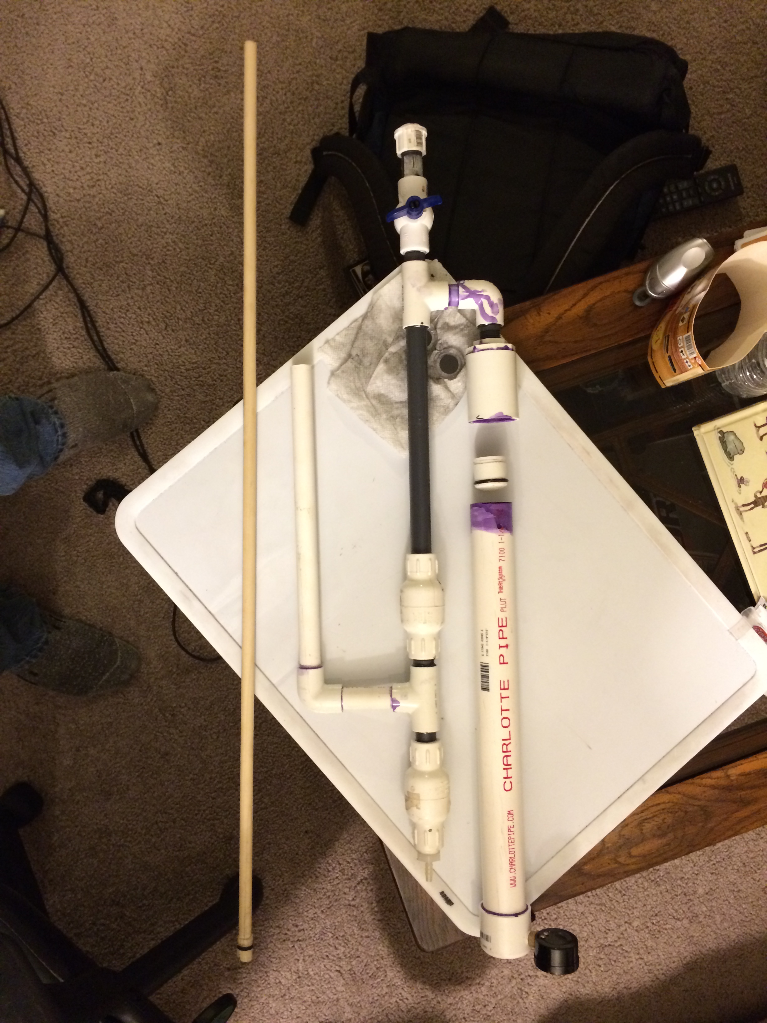
You can see here the piston head. It is a 3/4″ PVC Endcap with a small parting put into it via lathe. An O-ring is then fitted into that parting. The second parting was put in there before I had decided on the orientation of the endcap, in case I changed my mind.

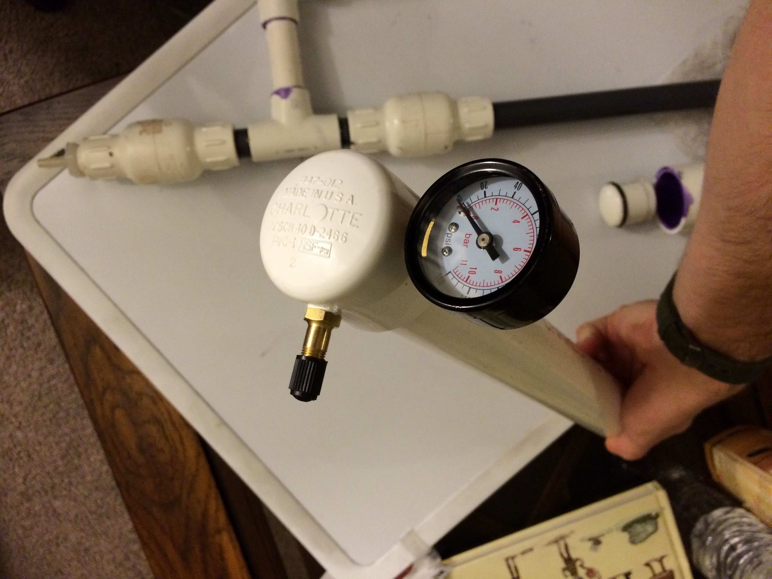
And here is the butt of the pressure chamber, showing the gauge and schrader valve.
Once assembled, it looked like this. You can see its size, as well. It it somewhat long and tall, but very skinny and light, and proves to be quite comfy.

Performance
Well, performance is still under testing.
At the moment I am prepressurizing the air to 30psi, and am pumping until 120psi is achieved.
Current figures rate a pressure chamber volume of 250mL, with a flow rate of about 350mL/second. Its range is nothing special- about 30ft. It takes seven pumps to fill the chamber up to 120psi.
Compared to the CPS-1000, it has nearly double the flow rate, but with under 1 second of firing time it needs to be used with care. Hopefully I will find myself in a water war again someday so I can see how it works there.
Engineering Model
Modeling this water gun has been rather interesting. It relies on a fixed amount of gas within in the piston, becoming a gas cycle of sorts. Unfortunately is not quite a Rankine Cycle, in terms of efficiency, as a good amount of energy is lost to waste heat from compression. To model the ideal gas within the air piston, first we are to simplify these equations.
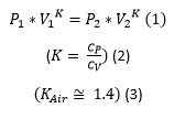
Becomes (4), adiabatic pressure equation assuming normal air.

Now, this can be simplified into a function of volume ratio and pressures, rather than two measured volumes (It can also use specific volume ratio-the two being equivalent- if that floats your boat).

The pressure model of the piston uses a combination of adiabatic and isothermal compression and expansion.
During compression, the compression is at a relatively low rate, such that the adiabatic effects of temperature increase are quickly eliminated as heat flows out into the environment. Since we then have a constant temperature and amount of gas, we can use the equation (6)

For safety concerns, I decided on a safe maximum operating pressure of 120psi, with an empty pressure of 30psi. Isothermally, this means a volume ratio (V_i/V_f) of 4. Upon firing, the air pressure is modeled adiabatically. This is due to the extremely fast discharge of water from the piston, lasting only about one second. It is then assumed that there is not enough time for significant heat transfer to occur, meaning there will be significant adiabatic cooling as the gas expands, resulting in a reduced effective pressure at the end of the piston’s travel. Using the previous equation (2) and our initial pressure of 120psi, and inverted volume ratio (as it is now decompressing; V1 is only a quarter of V2)
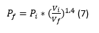
We find then that the resultant decompressed pressure to be approximately 17psi, an appreciable loss from the original 30psi. That being said, testing has shown that it is yet still a satisfactory pressure. Once firing is paused or completed, the heat flow into the piston quickly brings the pressure back to its corresponding isothermal levels.
For more information on homemade water guns, see SuperSoakerCentral’s post on the APH (A basic homemade water gun). It was a critical reference in the design and construction of the Gladius.
